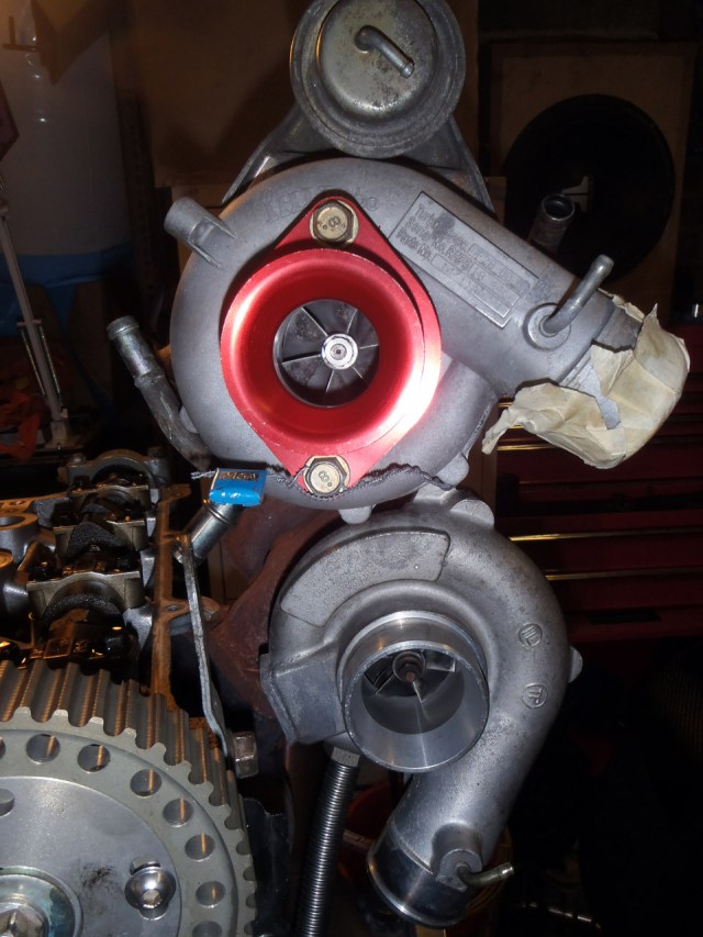
Whilst waiting for the replacement compressor housing, I refitted the previous one to simply protect the compressor wheel and help with mocking up. With the manifold still attached to the head and no real fitment issues for refitting the turbo I fitted the oil lines whilst the engine was out of the car.

Turbo fitted
Then refitted the engine. Whilst it was out I’d tried to tidy up the wiring a bit but there’s still more work to be done. Better than it was… not as tidy as I’d like.

Engine refitted
The problem here is the actuator, that’s in a very precarious place and may well foul the bonnet.

All the measurements I take suggest that is borderline on fitting, with the likelihood being on it not fitting. The last measurements I took suggested I had 16cm above the tub, and that’s about 19cm… but it sits further into the engine bay. If I use the highly scientific method of marking it on a stick, then putting the stick in the bonnet roughly where I think it will be, it’s pretty much exactly on that mark. If needs be, I might be able to re-use the previous actuator but it will need modifying and then I wouldn’t be able to go back to the TD04 if I didn’t like this turbo.
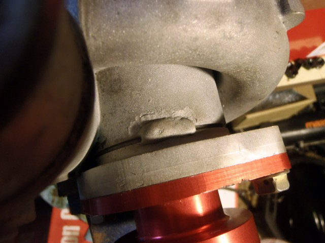
It wasn’t really something I could leave, so I made life awkward for myself and refitted the bonnet early. In a rare moment of luck, it seemed to fit! I could push down on the bonnet and make contact with the actuator but it didn’t seem to be resting on it normally. A quick camera down the gap at the scuttle end confirmed… not a lot.

I think it shows clearance but it’s quite dark. I may retake the photo with a torch shining on the area too.
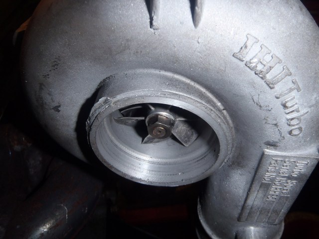
With the bonnet now nicely in the way and having to walk around it to get to the other side of the car I carried on refitting bits. The first was the downpipe where with a fresh new gasket it was happily bolted down and reminded me that there really is more to this that swapping turbos that have the same bolt patterns. The wastegate didn’t open very far!

Wastegate restricted…
It contacts with the flange on the downpipe. There’s a little bit of metal that could be removed on the flange but not a lot. Given that air doesn’t need much of a gap to flow out of I checked to see if the actuator even opened it that far. I connected a hose to the actuator and a foot pump and gave it a few psi. It opens pretty quickly and thankfully stops just shy of the blocked point:

… but within normal range.
The replacement compressor housing arrived so I fitted that and started putting all the hoses back together. Note I’ve connected the actuator directly to the turbo housing so I’ll only be running actuator pressure for now. About 7psi I think. This should be plenty for running in and it won’t have been remapped for the slightly bigger turbo so that’s ‘safe’.


As I mentioned, I think I’ve done a good job of tidying away the wires going down the sides of the engine bay but there’s still a long way to go.
With everything finished I filled it with fluids, removed the plugs and cranked it until I saw oil pressure. This took 20 seconds or so in total – I wasn’t brave enough to crank it for more than 5 or so seconds at a time. It got to 2 bar whilst cranking so happy with that. I refitted the plugs, crossed my fingers and cranked it again. It cranked, then backfired and I got scared. Cranked it a few more times and nothing but the occasional backfire.
Admitting defeat I grabbed the laptop and loaded up the ECU software. It wasn’t very good at cold starting before the build so I couldn’t rule in something I had done. I did a few tweaks – retarding the ignition, advancing the ignition, less fuel, more fuel but eventually the battery ran out. Another factor to add to the mix then – ECUs do funny things when the battery isn’t giving many volts.
I replaced the battery:

That should give me enough cranking to work out what was going on! Immediately it cranked much quicker… but still wouldn’t fire. The best I could do was get it to fire a little bit or ‘lock up’ and release a bit of smoke from the starter motor.
Back to basics I reloaded the map to undo all the messing around I’d been playing with. I could see that the ECU was losing sync every other revolution which suggested it wasn’t happy with the signal it was getting from the cam sensor in relation to the crank sensor. I checked the error code which suggested the same.
Then, embracing the 21st century, I resorted to data logging. Here’s one I prepared earlier, from last May, when it was working:

So the blue line is the crank sensor, and the green is the cam. The crank sensor has 4 nodes, with the cam having 1 then 2.
Here’s what I was seeing:
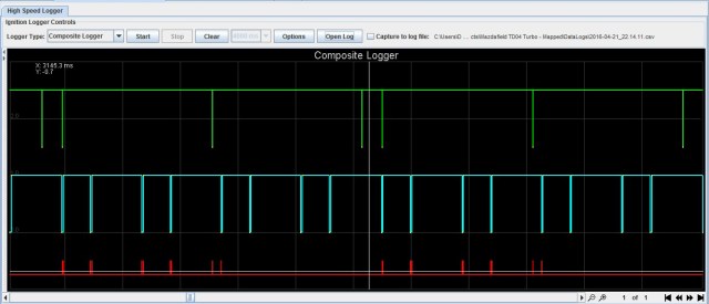
The cam signal has shifted in relation to the crank, which is probably the source of my troubles. Either the inlet cam has moved whilst I was refitting the cambelt, or I’ve fixed the trigger wheel on the crank wrong. There’s only four directions it can go so it was unlikely. However, it took a while to twig that the trigger wheel could go on backwards!!
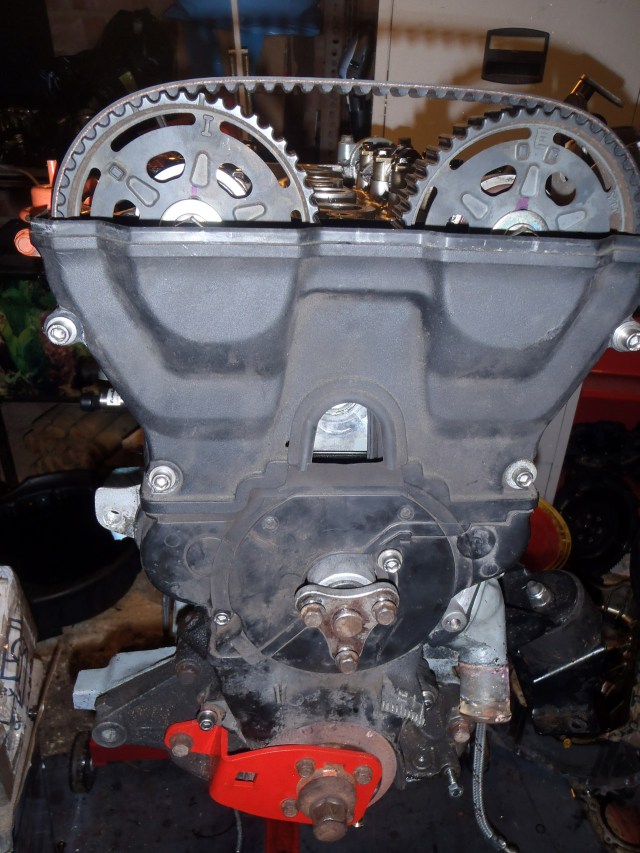
Which is exactly what happened. So here’s the trigger wheel as it is supposed to be attached to the cam pulley:
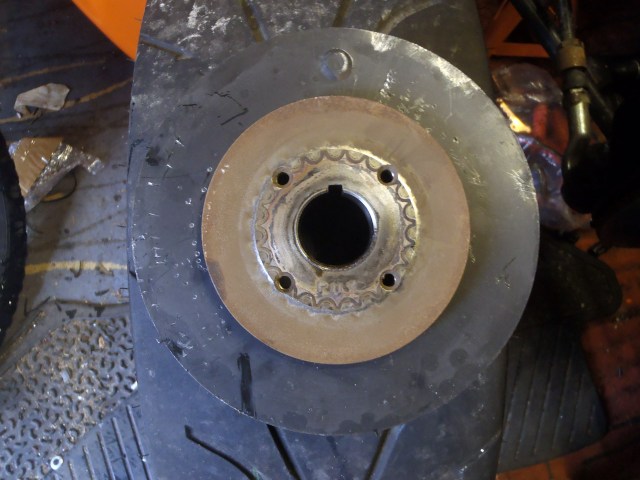
Not a great idea photographing it on a tyre, but you can make out some of the triggers. Just. Here they are marked up:
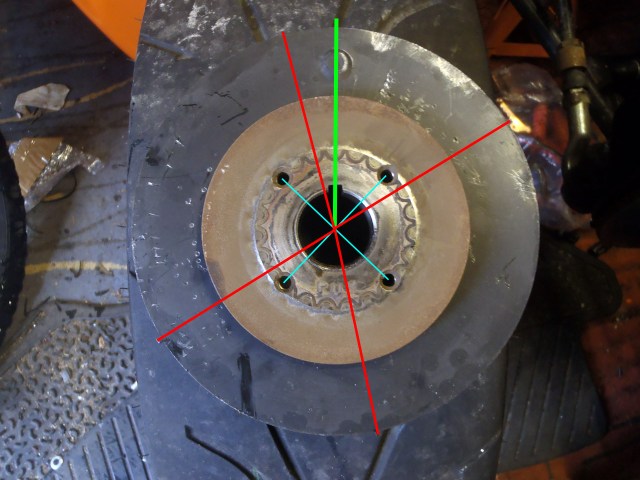
The blue is to help me find the centre. Green is TDC and red are the markings. If I’ve put that trigger wheel on back to front, all of a sudden that red line close to TDC becomes the other side which is what the logs were showing. Or in this case, as that photo seeing as we’re looking at the back.
I removed the alternator belt, unbolted the oil cooler and removed the crank pulley. I swapped the timing wheel around (now spotting there’s a dimple at TDC which should be on the back), reassembled it all and hey presto. A working engine! Needs a bit of throttle to start but that’s a fuelling issue which can be sorted.
Just the small matter of running in and an MOT before mapping!