Sump refitted, boost control solenoid

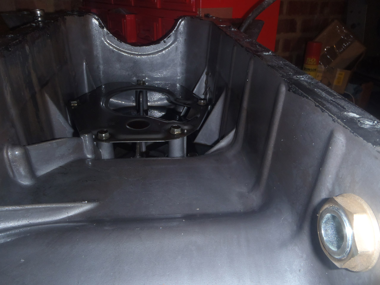
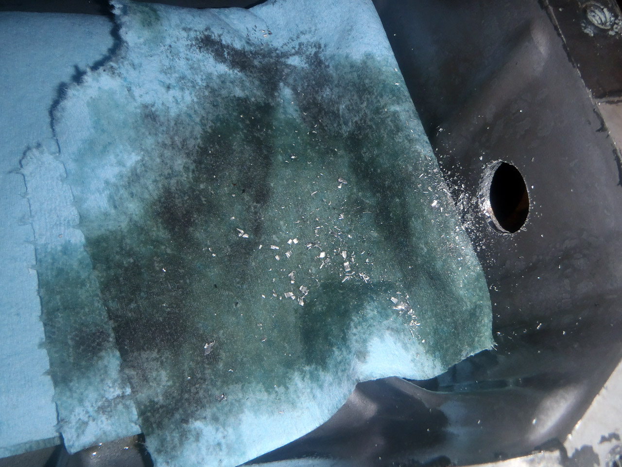
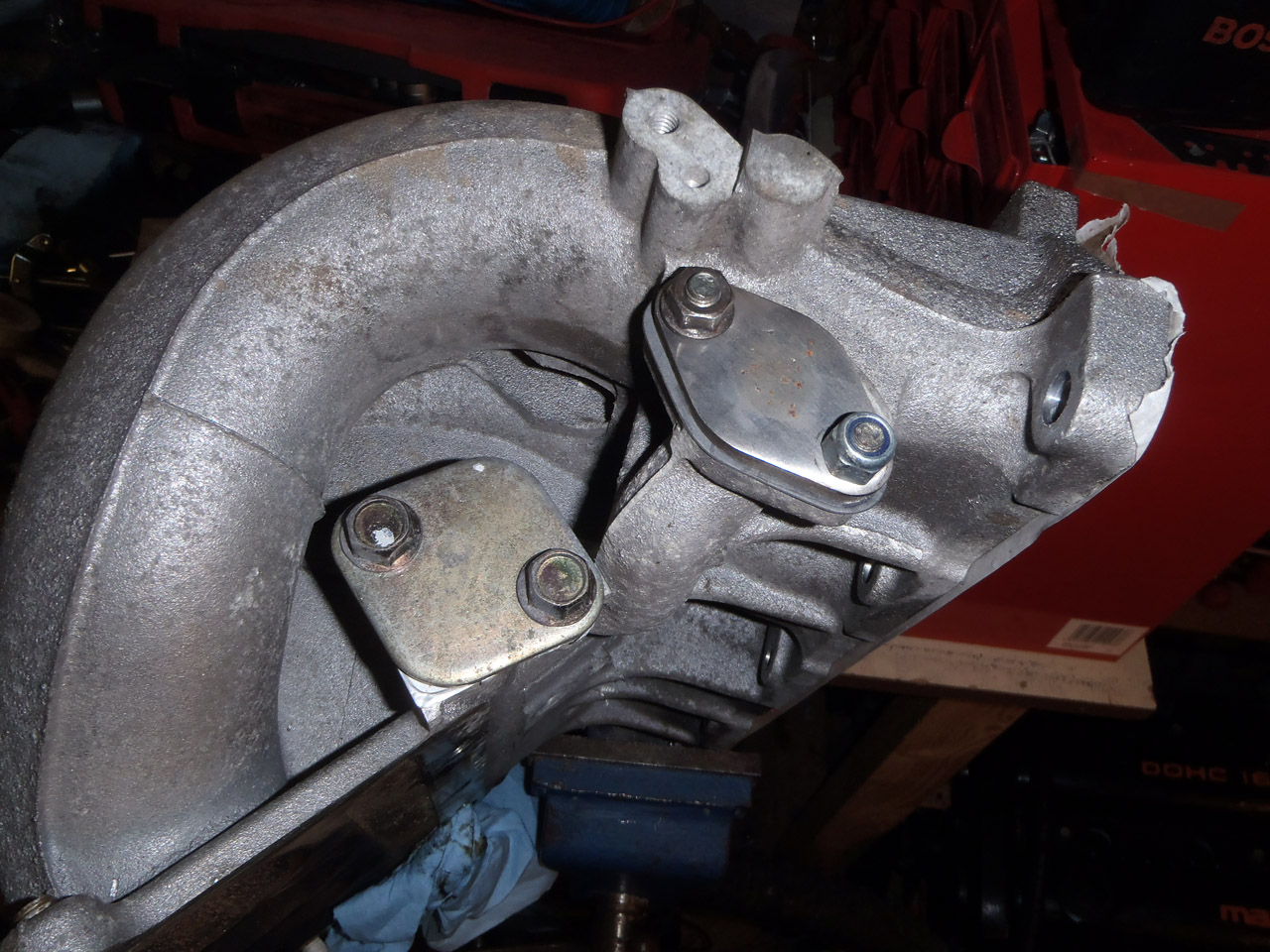
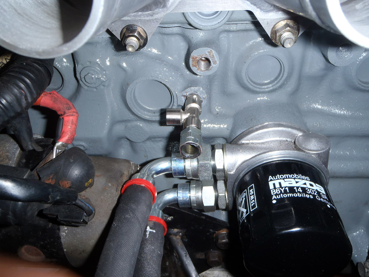
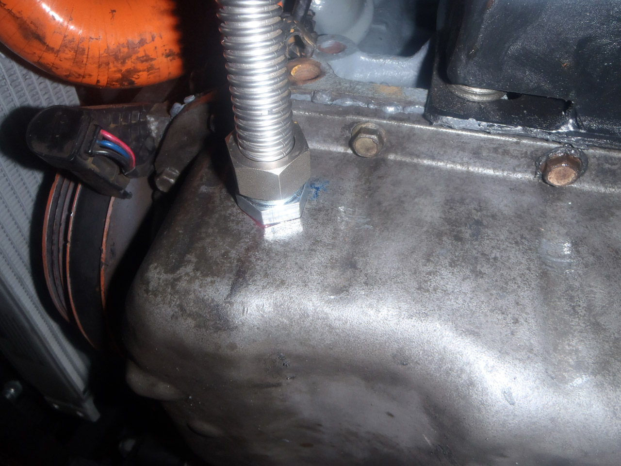
Ok, sump is back on, and it wasn’t too bad. Initially I was worried that it wasn’t going well, I just couldn’t get the corner the drain fitting was in to sit flush with the engine. Then I realised I had trapped the drain hose in between the sump and the block. Oops!

As expected, some of the bolts a pig to get to and I’m surprised my arm didn’t fall off from all the spannering in confined spaces. Test fitted the drain hose and all seems fine with the world.

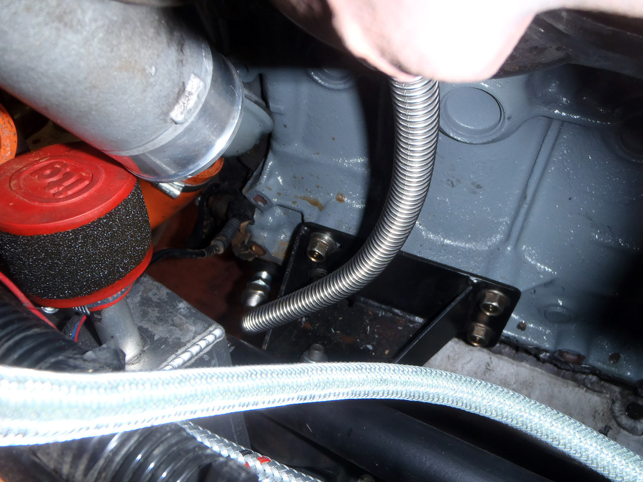
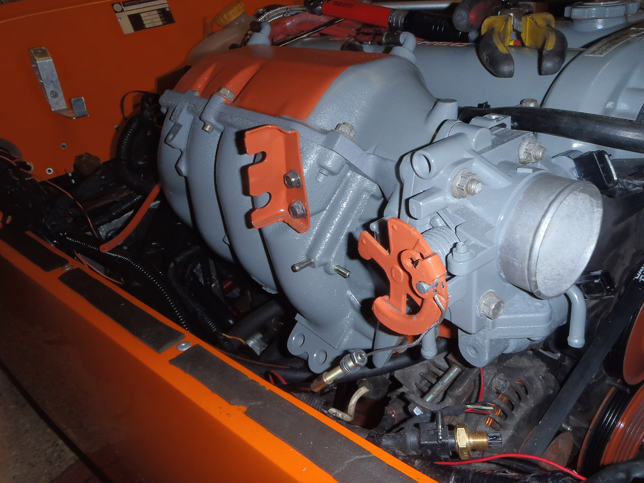
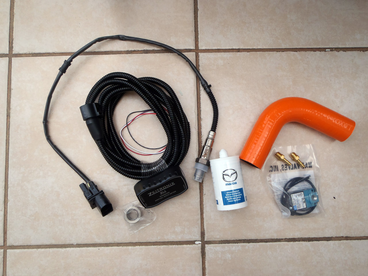
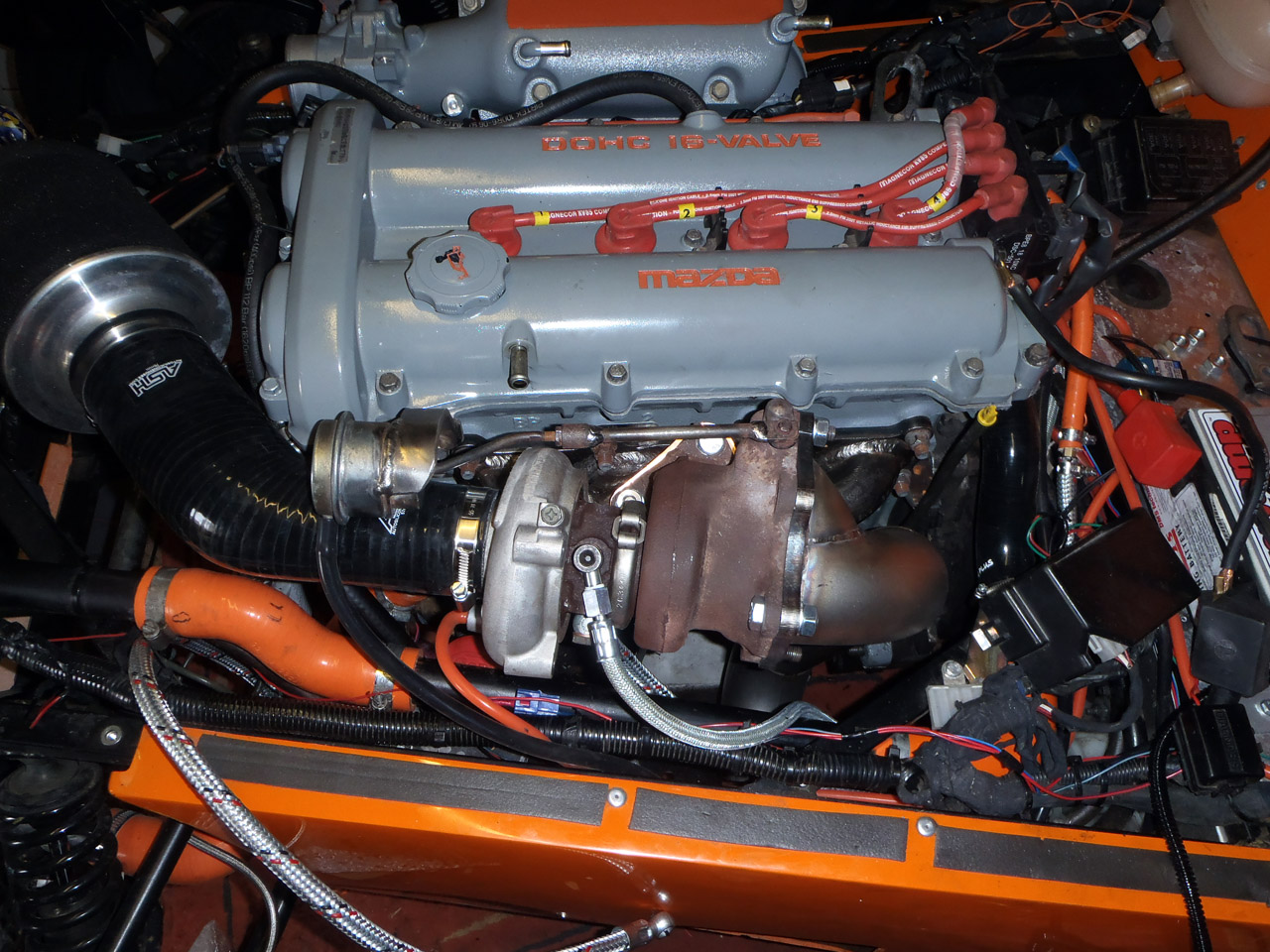
Also got on with plumbing in the boost control solenoid. This is what will allow be to increase the boost pressure above standard wastegate pressure and turn my engine into a really cool firework. I’ve fixed it in place with velcro tape.

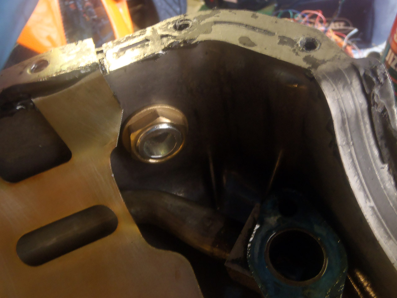
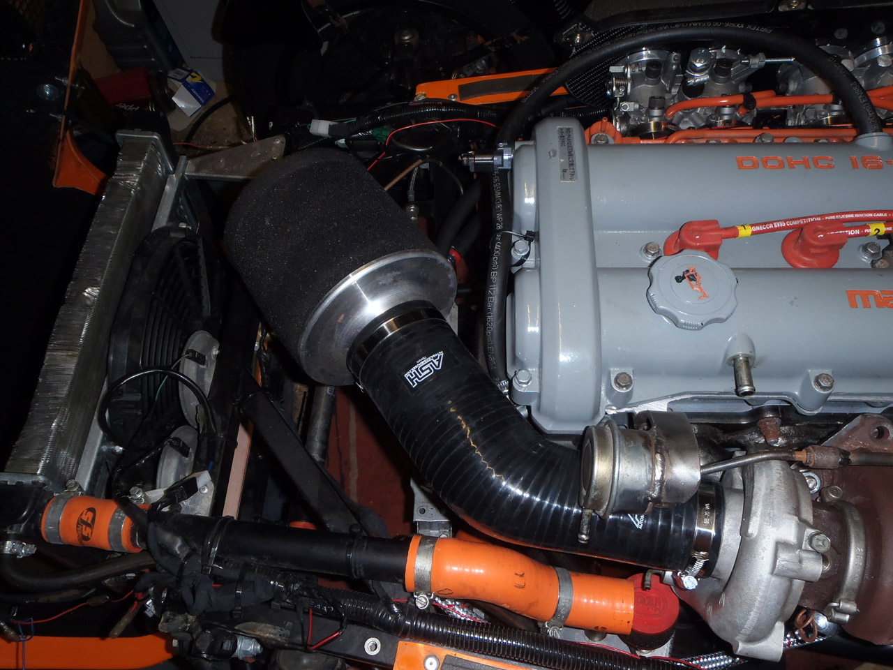
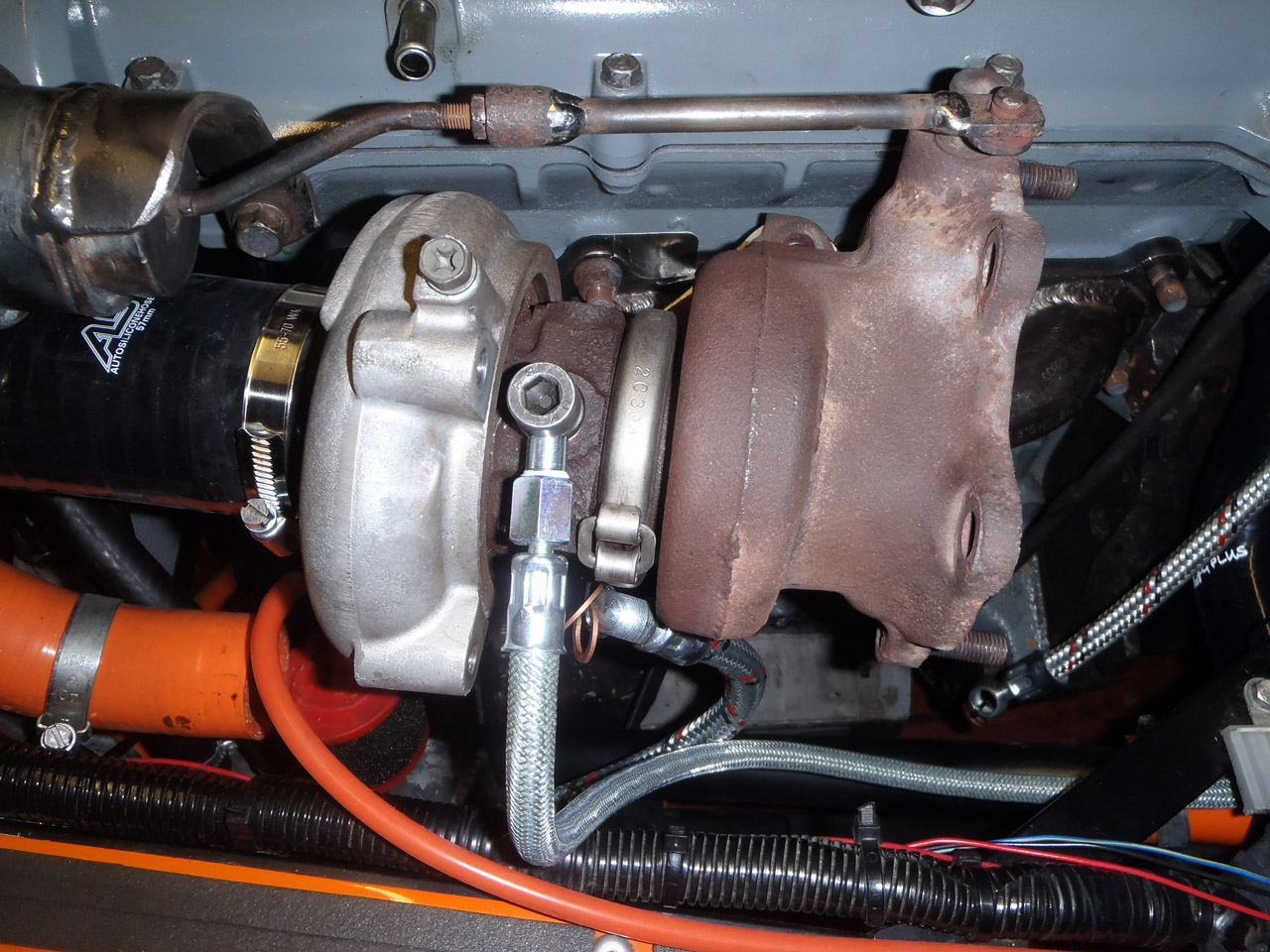
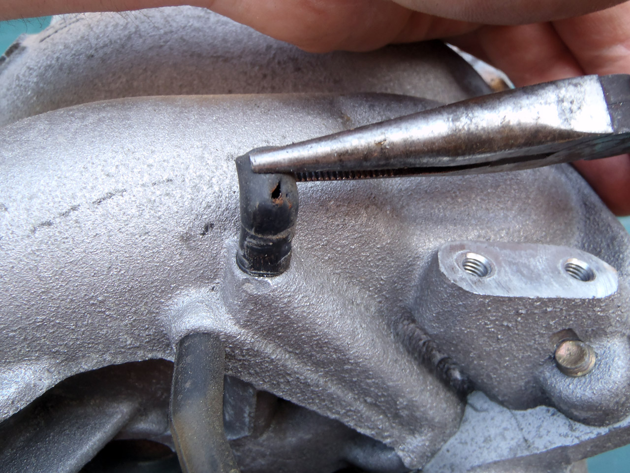
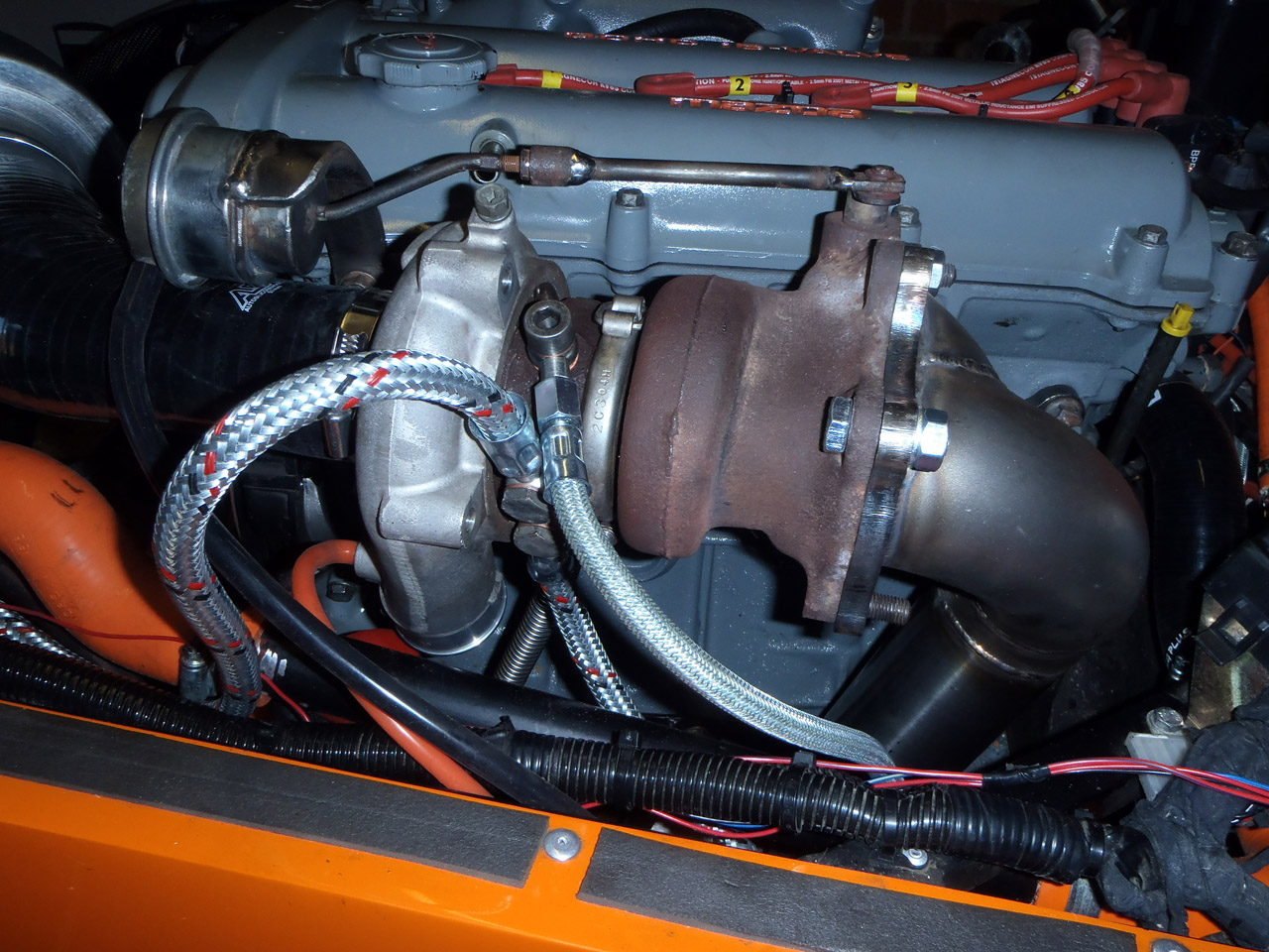
With no need to remove the turbo any more, I fitted it with self locking nuts. The idea being they shouldn’t loosen themselves during track work like normal ones are prone to doing. Whether there’s enough thread showing through to lock them enough I don’t no. I also fitted the coolant supply hose and the oil supply hose. I’d have fitted the coolant return hose too, but I’d some how managed to lose the banjo bolt.

A quick search on eBay only turned up banjo bolts from Hong Kong and Japan, which is a bit weird. It was about then I found some new motivation to go and find the Houdini-bolt. It had some how managed to jump off the workbench onto the floor, then run back under the workbench under stuff that hasn’t moved for months. Of course, I didn’t find this until I’d gone through the pain of clearing the workbench and still not finding it.

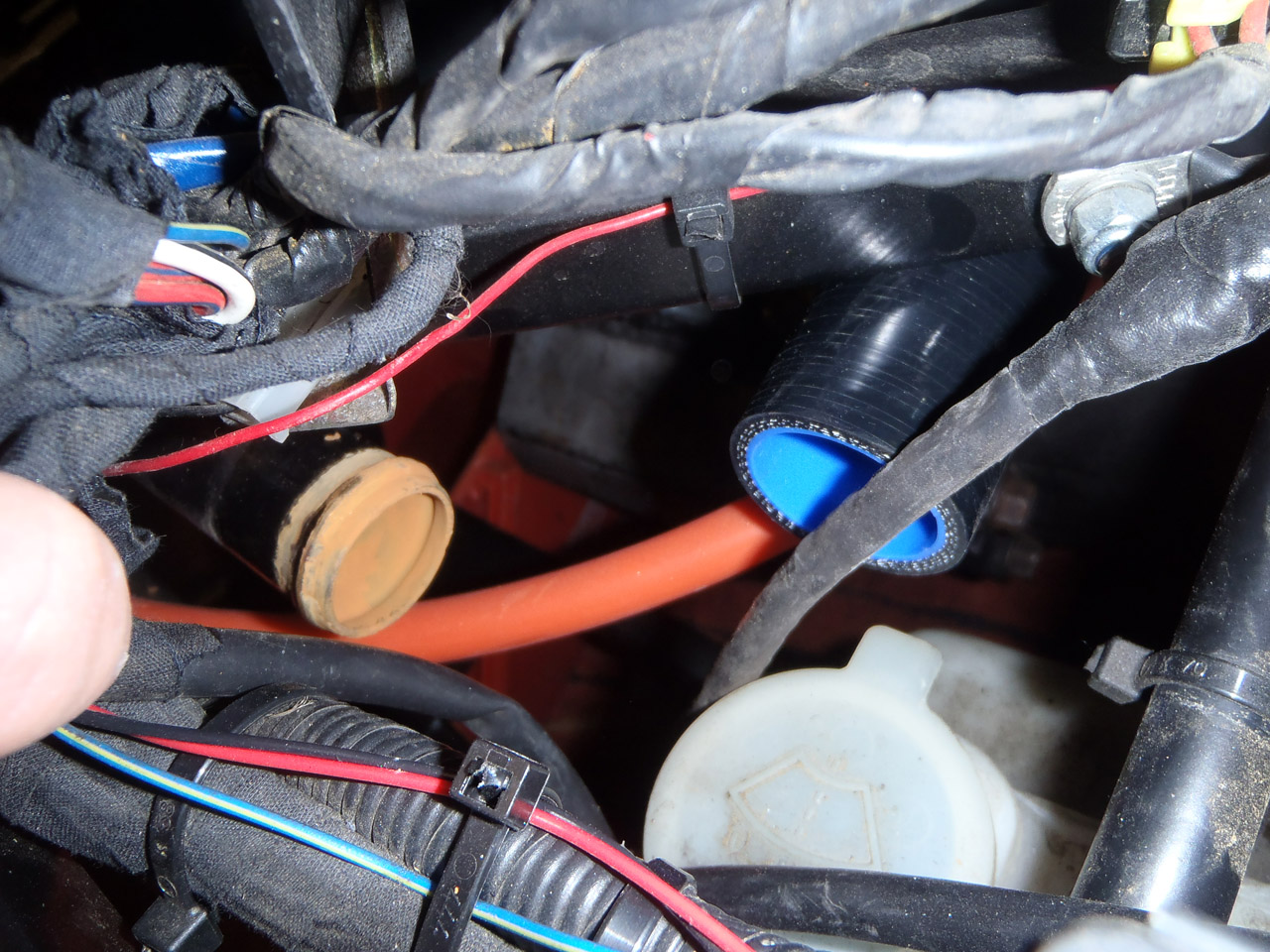
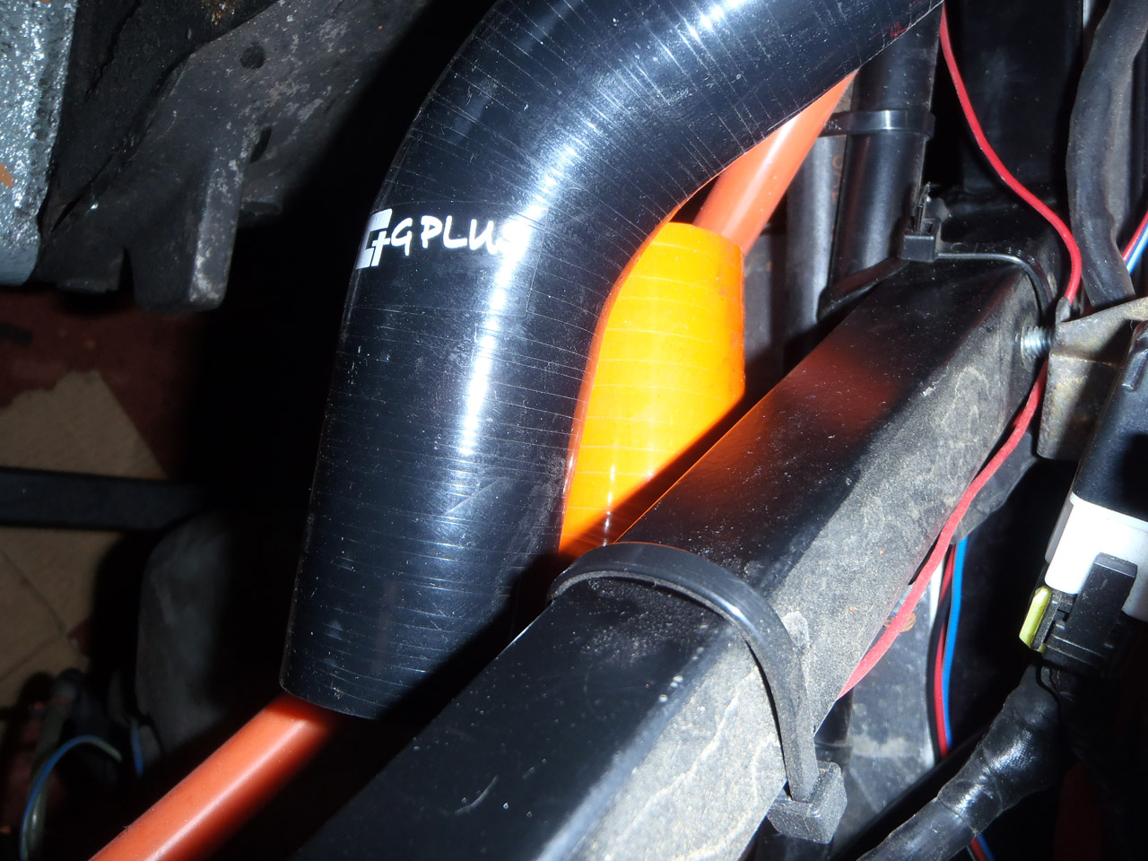
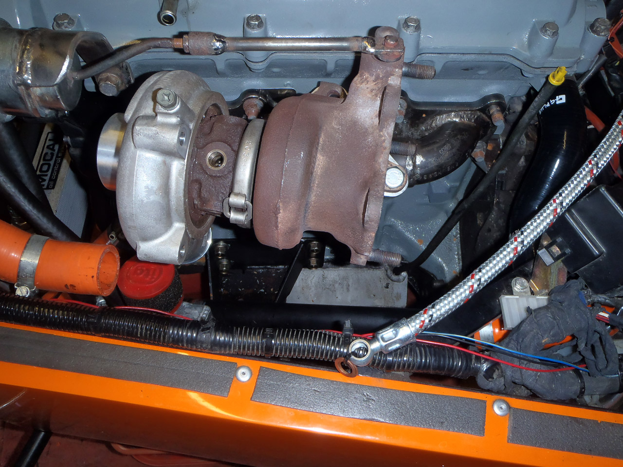
I fitted the coolant return hose. Because of the way the turbo is orientated it necessitates it pointing vertically. Luckily it can loop back down before hitting the bonnet.

With that done, I can now look to getting some heatproof sleeving for all the wires and start to tidy it all up a bit.

Oh I’ve also finished moving that coolant pipe, but it doesn’t photo very well so no pics I’m afraid.

Posted in Performance upgrades | Leave a comment

Oil return fitting

Just a quick update this one. There was talk on the WSCC forum about the oil return possibly being too low and so submerged in oil. This would cause pressure to increase in the oil return which in turn could well force oil through the seals of the turbo. When I first drilled the hole I was sure I was well above the oil line, but I hadn’t put any science to it so I could have made a mistake. I did a bit more searching today and the most stringent of all suggests is to drill with a centre no lower than 2″ from the sealing flange. Good news, I was well within that.

I refitted the dipstick and looking down the sump you can also tell that I’m some way above the normal oil line.

Some of the internet pages on the subject suggests going too high will put you in conflict with the oil pickup pipe. This was more of a worry than the height of the hole. I thought I was far enough forward but of course the pipe goes from the back to the front of the engine. I quickly removed the pickup pipe and windage tray and dropped them into the sump:

Whoops! Ah well, luckily a long way from the pickup pipe so I modified the windage tray slightly.

As has been present through these photos the nut for the back of the fitting arrived today. This isn’t to hold it in place, it’s just for another opportunity to seal the hole to stop any oil leaks. I put some threadlock on the threads and sealant on the flange of the nut then did it up. Hopefully this will do the trick.

Posted in Performance upgrades | Leave a comment

Turbo oil drain and inlet manifold

Lots of little jobs done recently. Including drilling the sump for the turbo oil return. Some of the MX5 guys swear that by blowing air through the oil filler cap you can drill the sump in situ without worrying about swarf. I’m not convinced, so I removed it first. Not without checking where the hole should go mind.

Removal was a mission in itself, with two bolts being handily boxed in by the drivers side engine mount and the wings of the sump:

I had to support the engine on a trolley jack, remove that engine mount, remove those two bolts, refit the engine mount and then carry on. It wasn’t too bad, once I’d remembered the bellhousing bolts. Refitting is going to be a pain though.

With the sump off I had a look at where I had marked to drill.

I thought it was a bit high, by the time the hole had been drilled it would have been quite close to the top. So I shifted it down a bit, and also more into the middle of the flat bit. Taking my brave pill, I proceeded to put a hole in my sump.

No turning back now, so I made the hole steadily bigger until it was 19mm, ready for tapping (1/2 bsp).

As expected, this had put a lot of swarf in my sump. In a bid to catch it, I’d lightly oiled a bit of tissue in the hope that most of the swarf would stick to it. Here it was after the first hole:

And after the last:

I definitely wouldn’t want to risk that by drilling without removing the sump.

I tapped the hole:

And attached the fitting, using threadlock resistant to oils:

Theoretically, the threadlock should stop oil leaking through the threads, but just in case I’ll smear silicone sealant around the edges of the hole then fit a nut to hold it all in.

Another job done was to remove the throttle bodies, paint the standard inlet manifold and fit that. Before painting I removed the EGR pipe blank from my mk1 manifold and fitted that. I also found and EGR valve blank on a mk2 manifold I had lying around, so fitted that too.

I painted the inlet manifold grey and orange to match the engine, but it’s not turned out as well as I’d hoped. The curse of not planning ahead! The orange section on top of the manifold is supposed to house a sticker which I’ve not chosen yet, but the orange bracketry hasn’t worked well at all. Looks a bit… fisherprice…

Other jobs include:

  • Torquing the exhaust manifold
  • Wiring in the boost control solenoid
  • Wiring in the wideband lambda sender
  • and removing the polo rad… to find one of the top mounting brackets had snapped. Doh! New one ordered.

Exhaust is booked in to be made next week. Should probably book mapping in soon too, perhaps for w/c 6th July. Hopefully that will allow enough time for the intercooler to arrive and get some hoses to connect it all up.

Posted in Performance upgrades | Leave a comment

Air filter and turbo oil feed

Just the one part arrived today – the 45 degree reducing elbow to join the air filter to the turbo inlet. Unfortunately, ASH hoses only do these in black. I’m undecided if I’ll order and orange one later down the line.

It fits quite well:

There’s two points of contention. The first is it’s quite close to the port on the actuator, I may bend that bracket up slightly. The other is I need to tweak the catch tank lines slightly but that’s no biggy. When the intercooler arrives I’ll be able to tell how much it interferes with the routing of that.

It rounds the corner of the engine nicely, but does mean there’s no real scope to pull it back a bit to try and generate more space up front.

You can only just see it, but it sits the filter underneath the fibreglass bit of the bonnet. This should protect it from rain if it’s parked up outdoors.

I also found some motivation from somewhere to fit the oil feed pipe. This comes from the pressure sender port on the other side of the block. I popped off the throttle bodies and removed the current pressure sender and adaptor. I then assembled the T-piece that came with the kit, using a small amount of PTFE tape. For each join I double checked that there was a good enough connection for the pressure sender to earth to.

I attached the hose, ran it around the back of the engine and it fits onto the turbo fine:

Hopefully I can get some paint on the inlet manifold this weekend, then I can fit that. Other task to do is one of the ones I’m not looking forward to – drilling the sump.

Posted in Performance upgrades | Leave a comment

More coolant progress and inlet manifold cleaning

Parts have been arriving over the last couple of days. First up was this:

I wanted the S-shaped hose you use at the bottom of the radiator but could only find new-old stock rubber ones on eBay. However, there are some similar ones for the Datsun 240z, just a big longer. I ordered a kit of them so that I could cut them to size. Having two in the kit just meant I had a spare! £23.40 so well priced.

I popped it onto the thermostat housing and it comes quite close to the end of the pipe I’ve moved:

Certainly too close to get a 90 degree silicone bend in there! As above though, it will get trimmed to fit.

Today, the following arrived:

So that’s (from right to left)… a wideband oxygen sensor so I’ll know I’m going to blow the engine up before I blow it up (with boss to get welded onto the downpipe)… sealant for the sump as I’ll need to take that off to drill the fitting for the turbo oil drain… 90 degree silicone bend to compliment the hoses above… and a boost control solenoid. This will be so I can go above normal wastegate pressure (which I think is about 7psi).

I test fitted the 90 degree bend and as expected, they overlap a LOT.

This picture shows they are level vertically though which is good news. I’ve not trimmed them down because I’m still waiting for the joiner to be delayed. Ash hoses have helpfully told me it’s been delayed but not actually said when it has been delayed until.

I popped the downpipe back on and the coolant lines are well clear:

After that err… minor progress, I randomly turned my attention to the inlet manifold. I don’t trust my bike throttle bodies to hold boost! I’ve got the inlet manifold from the mk2.5 MX5, often referred to as the flat top. The American MX5/Miata guys go mad for these so there must be some benefit to running them. The benefit for me is that it fits…

I started to strip it down to clean it up before painting it. A good thing I did really, else I’d never have spotted this:

That would have been a tricky to find boost leak, if I’d even notice it at all.

A few bolts and clips later and it was disassembled.

Not exactly the cleanest of things in there:

Lovely. I cleaned it up and will try and get some paint on them at the weekend.

Before I finished for the day I had a quick look at the coolant lines for the turbo. As expected, the inlet one wasn’t long enough:

But the outlet one was fine:

Not the fault of the guy who made the kit. Normally the thermostat bypass lines are at the front of the engine. I just happen to have moved the thermostat to the back of the engine to compensate for there being no heater.

Posted in Performance upgrades | Leave a comment